ALU Control
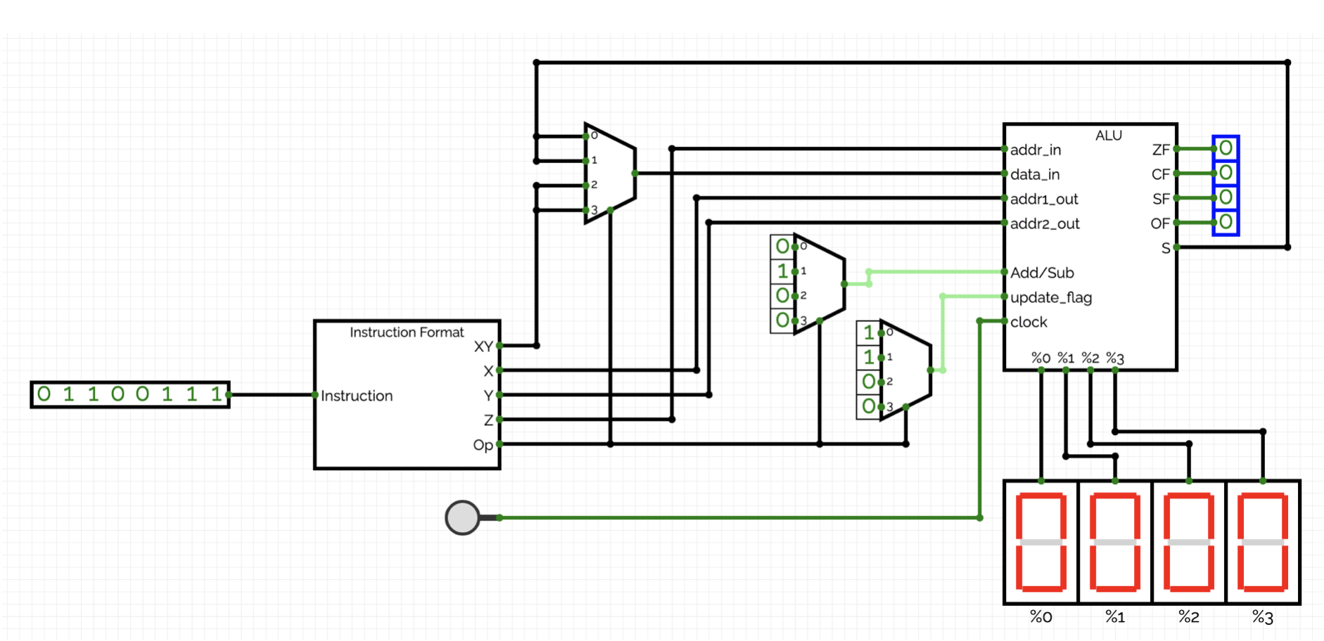
In the (for today) final step, a circuit can now be created so that depending on the Op-code and the operands X, Y, Z, and XY, the following commands for controlling the ALU are supported:
|
00 |
Add the contents of registers %X and %Y and write the result to %Z. Update the status flags accordingly. |
|
01 |
Subtract the content of register %Y from %X and write the result to %Z. Update the status flags accordingly. |
|
10 |
Write the bit pattern XY to register %Z. |
|
11 |
Not currently in use (currently identical to Op = 10). |
For an Op-code of 00 (Addition) or 01 (Subtraction), datain is connected to the output s of the ALU. The result s will thus be written to the destination register %Z at the next rising edge of the clock signal. For an Op-code of 10 or Op-code of 11, datain is connected to XY. At the next rising edge of the clock signal, the bit pattern XY will be written to the destination register %Z.
The status flags are only updated after an addition or subtraction.