Crash Course in SystemVerilog: Combinatorial Logic
We've seen that circuits consisting solely of logic gates can be described by Boolean functions or truth tables. It is said that these circuits can be described through “combinatorial logic.” For example, the following circuit can be described with the equations \(\text{out1} = a \land b \lor a\) and \(\text{out2} = a \lor b\):
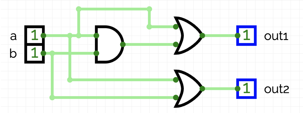
In practice, such mathematical descriptions are implemented using HDLs (Hardware Description Languages). For instance, the above circuit can be described as a module in the SystemVerilog language as follows. The logical equations appear within the always_comb block:
1 2 3 4 5 6 7 8 9 10 11 12 13 | module Example1 ( input logic a, input logic b, output logic out1, output logic out2 ); always_comb begin out1 = a & b | a; out2 = a | b; end endmodule |
In the following example, the described circuit has not been altered; only new designations have been introduced:
1 2 3 4 5 6 7 8 9 10 11 12 13 14 15 16 17 18 19 20 21 | module Example2 ( input logic BTN1, input logic BTN2, output logic LED1, output logic LED2 ); logic a, b; assign a = BTN1; assign b = BTN2; logic out1, out2; assign LED1 = out1; assign LED2 = out2; always_comb begin out1 = a & b | a; out2 = a | b; end endmodule |
The module's inputs are now named BTN1 and BTN2, while the outputs are named LED1 and LED2. Internally, these have been assigned with assign to the alternative designations a, b, out1, and out2. The described combinatorial logic remains unchanged.