Delays in Logic Gates
Describing logic gates with Boolean functions is a mathematical modeling approach. This model assumes that a logic gate instantaneously provides the output. However, in reality, this only occurs after a certain period of time (in the nanosecond range). A more accurate model can be obtained using differential equations, which describe how analog values (voltages and currents) change in an electronic circuit. An analog value, such as voltage, is then assigned a digital value:
-
If the voltage is below a threshold \(U_0\), the state is interpreted as 0.
-
If the voltage is above a threshold \(U_1\), the state is interpreted as 1.
-
If the voltage is in the range of \(U_0\) to \(U_1\), the digital state is undefined (usually denoted as x). However, in a logic gate, after a certain period of time (the “delay”), the state is always defined, either 0 or 1.
For our purposes, modeling logic gates with Boolean functions is usually sufficient. However, it is helpful to know the limits of the model. In CircuitVerse, you can consider the delays of gates in the simulation for this purpose.
Instructions
Build the following circuit with two NOT gates in CircuitVerse:
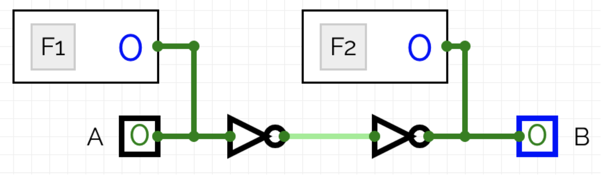
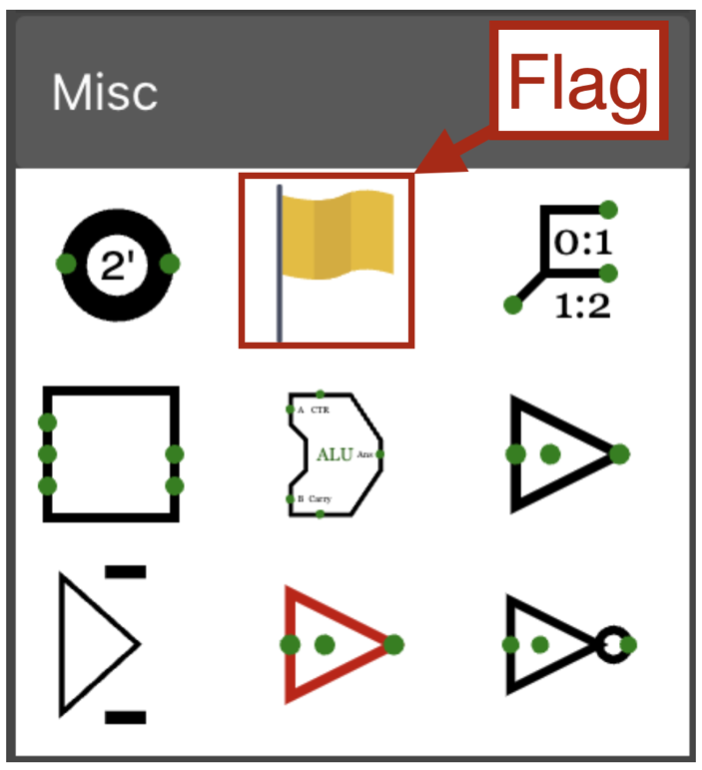
The symbols labeled F1 and F2 are called flags, which can be found under “Misc” (in the “Properties,” you can change the labels under “Debug Flag Identifier”):
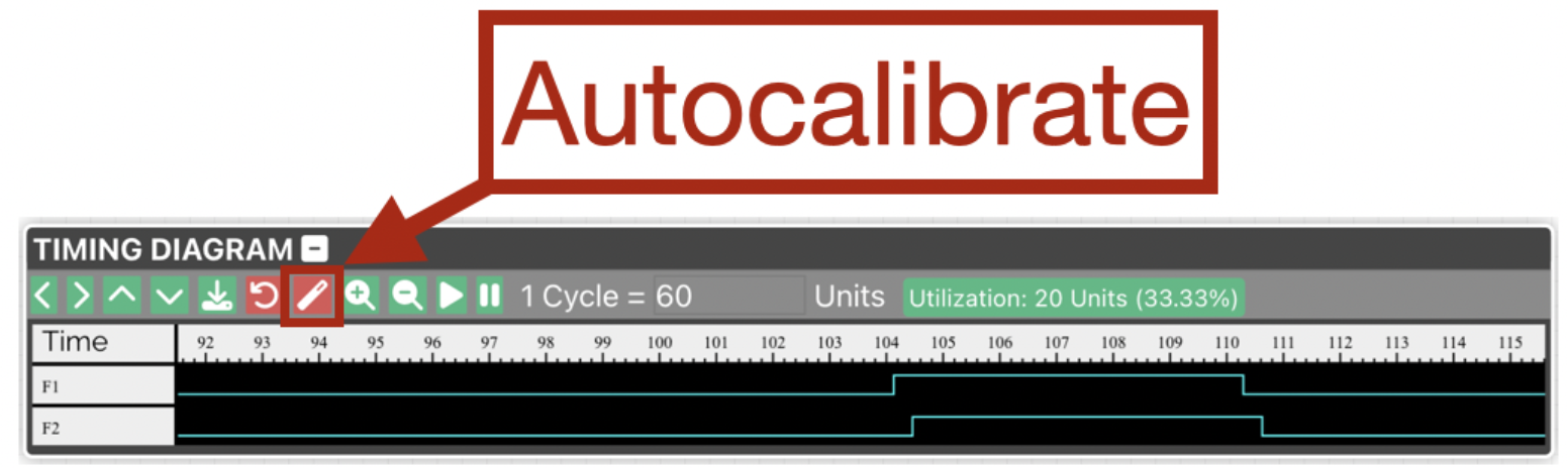
When modeling the logic circuit with Boolean functions, input A and output B always have the same value. However, to see that there is a delay in reality, you can observe the timing diagram in CircuitVerse:
-
Click on “Autocalibrate” in the timing diagram.
-
Change the value of input A from 0 to 1 and then back from 1 to 0.
The timing diagram displays the value extracted from F1 and F2 over time. By default, each logic gate in CircuitVerse has a delay of 10 nanoseconds. You can change this under “Properties” by clicking on a logic gate.