D-Latch
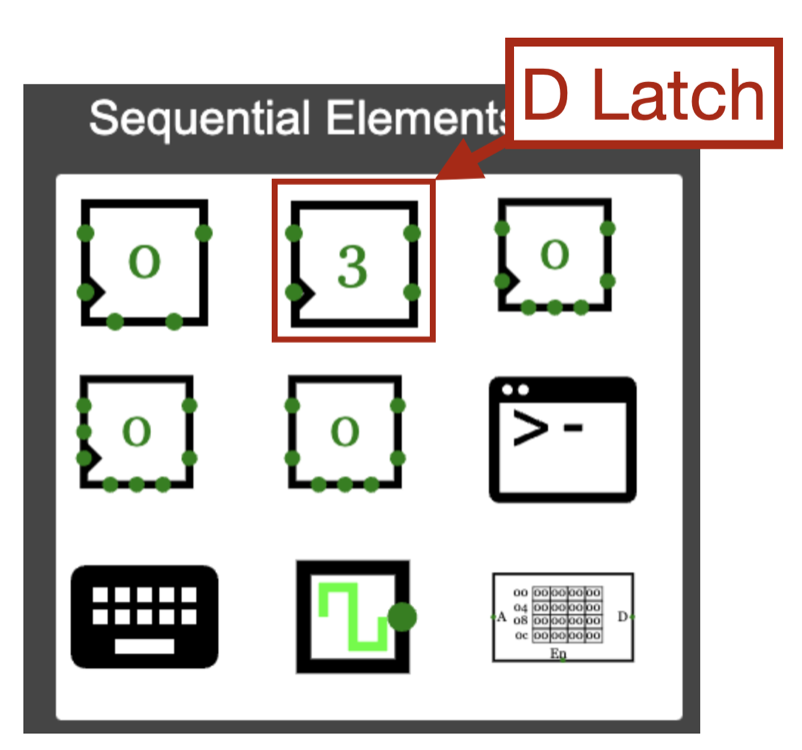
To build a computer, we need components (we will use so-called D flip-flops) to store results for further calculations. To gain insight into this topic, let's start with the so-called D-Latch. You can find this in CircuitVerse under Sequential Elements.
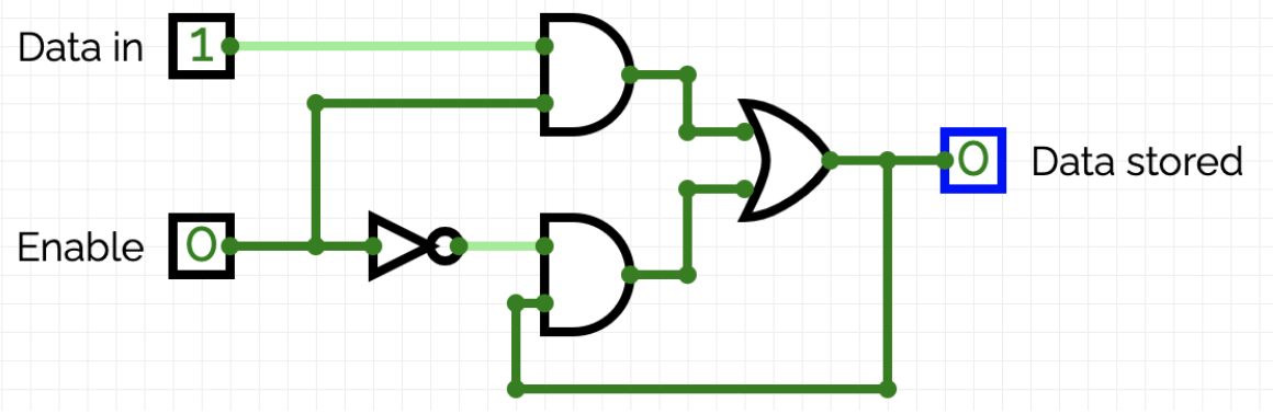
The functionality can be experimentally derived with the following circuit:

Here's what you should observe:
-
If Enable is set to 1, the value of Data in is transferred to Data stored.
-
If Enable is set to 0, the value of Data stored remains unchanged, regardless of the value of Data in.

Mathematically, this can be characterized by:
\[\text{Data}_\text{stored} = \text{Data}_\text{stored} \land \lnot \text{Enable} \lor \text{Data}_\text{in} \land \text{Enable}\]One cannot solve this implicit equation with respect to \(\text{Data}_\text{stored}\). Therefore, a D-Latch cannot be described with a Boolean function. However, we can attempt to implement this equation using logic gates as follows:
Tasks
-
Implement the circuit in CircuitVerse. Confirm that the circuit behaves like the D-Latch.
-
Change the delay of the NOT gate to 20. The circuit should no longer behave like a D-Latch.
-
The above equation characterizes a D-Latch, but there is no instruction on how to implement it. For a stable implementation, the delays of the gates must be taken into account. We will not delve into this aspect in this course. However, a possible implementation should not be withheld from you:
Note
The rule of thumb applies:
-
What doesn't work in the simulator also won't work in reality.
-
What works in the simulator may work in reality, but it's not guaranteed. Because a simulation is ultimately a model that simplifies reality.