Clock-Controlled Counter
Later on, we'll use D flip-flops in our computer for CPU registers. However, first, let's see how we can combine the combinational logic of an adder with the sequential logic of a D flip-flop. To do this, build the following circuit with a 4-bit adder and a 4-bit wide D flip-flop:
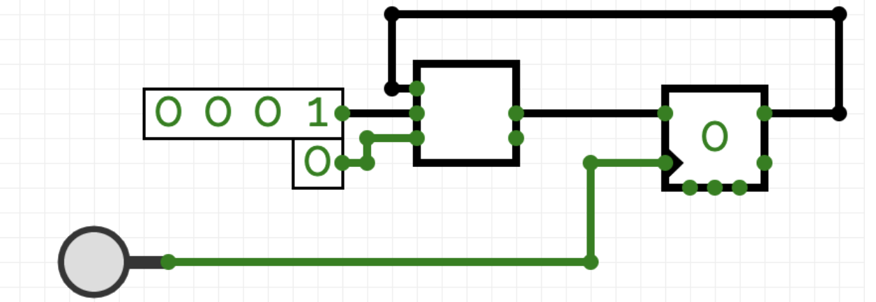
While experimenting, you should observe that the value stored in the flip-flop increases by pressing the button. From this, one can infer that the maximum clock frequency depends on the length of the longest logic path. If the delay of the adder were modeled more accurately and the button were pressed too quickly, the “counting up” would not work.
Also, understand why a D flip-flop is necessary in this circuit and why it wouldn't work with a D latch. To do this, replace the D flip-flop with a D latch and test the circuit.