Half Adder, Full Adder, 4-bit Adder
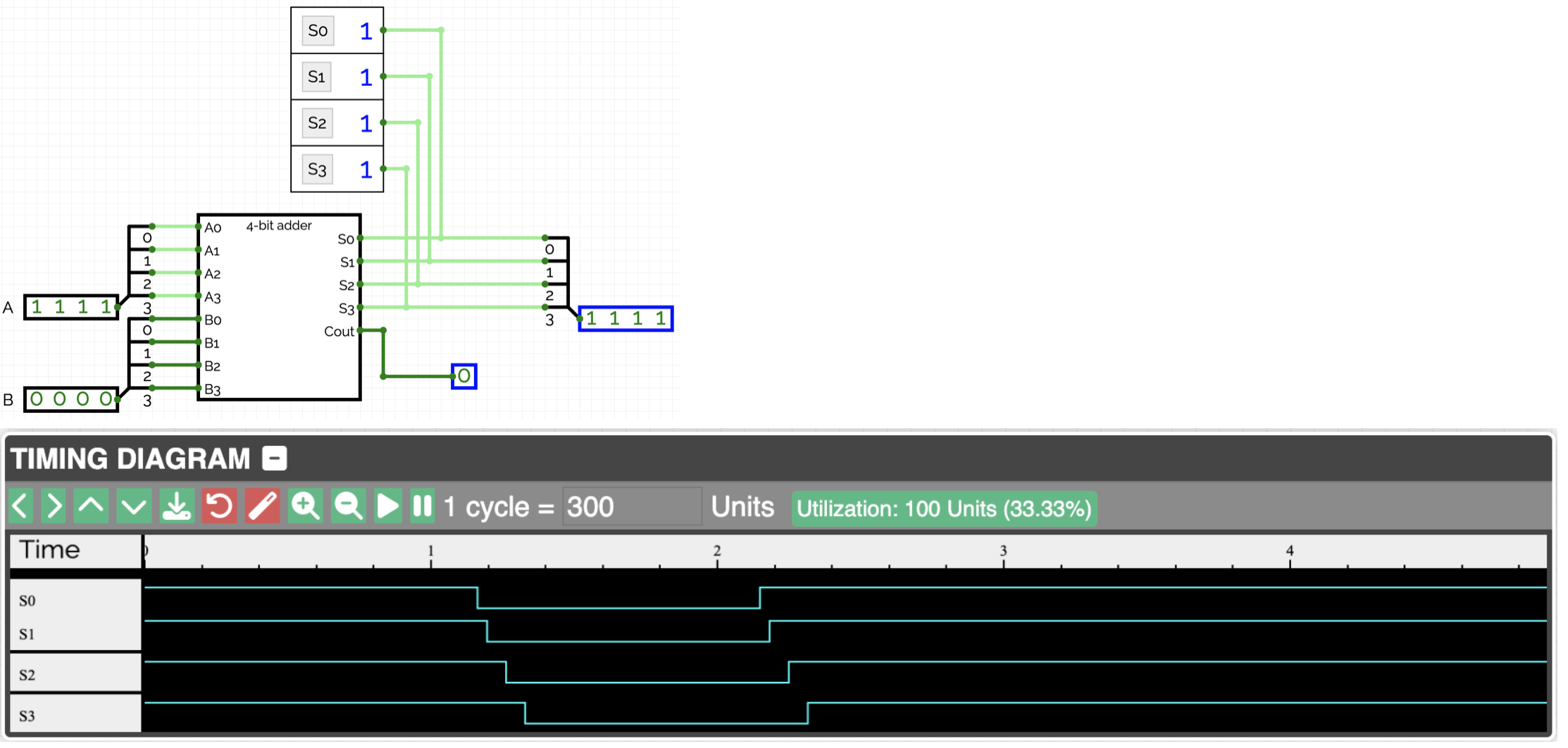
Next, let's observe the effect of delays in our 4-bit adder. An interesting case occurs when the bit pattern 1111 is added to the bit pattern 0001. The correct result is then 0000 (with a Cout value of 1). However, observing the bits of the result, it initially takes the value 1110, then 1100, then 1000, and only then does it reach the final result 0000.
In practice, delays affect the maximum clock rate of a computer. Depending on the “length of the logic paths,” one must wait more or less time before a result can be used for another calculation.
To observe the described effect, we will build the 4-bit adder described in the lecture and then use flags and the timing diagram.
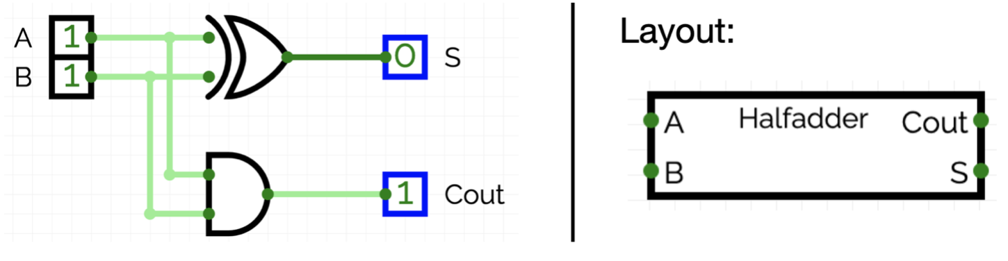
Half Adder
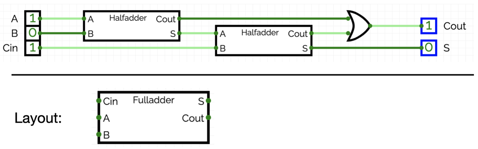
Full Adder
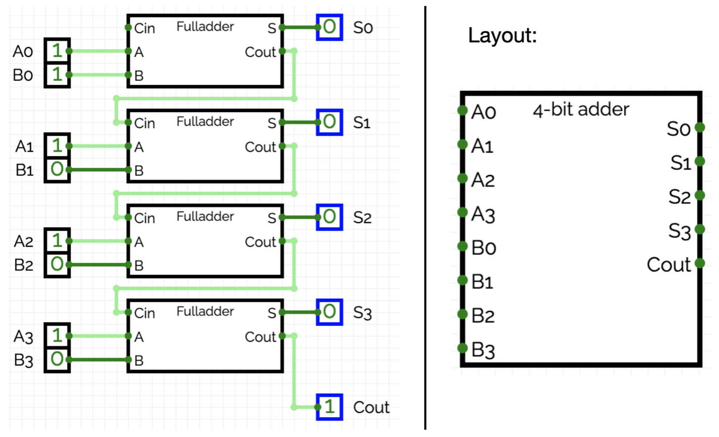
4-bit Adder
Experiment
Our 4-bit adder is a so-called Carry-Ripple-Adder. There are also adders that use more efficient algorithms, such as the Carry-Look-Ahead adder. These adders can calculate the result faster by intelligently precomputing the carry bits. The various algorithms also differ in the number of logic gates required for their implementation. It is important to understand the advantages and disadvantages of the different adder algorithms to choose the appropriate implementation for the specific application.